Modern data centers operate under thermal conditions that leave little margin for error. As rack power densities climb from a historical average of 5 kW to contemporary loads of 20 kW, 30 kW, and beyond, the control architecture governing data center cooling equipment becomes the decisive factor in maintaining uptime, thermal stability, and energy efficiency. This article provides a rigorous technical examination of data center CRAC control and the broader family of cooling topologies, covering closed-loop control principles, sensor placement, governing standards, and structured troubleshooting protocols relevant to electrical design engineers, facility managers, and HVAC maintenance technicians. Because CRAC and CRAH units rely on variable frequency drives, harmonic management is an integral part of reliable cooling control; see our guide on VFD Harmonic Mitigation in Cleanroom and Data Center HVAC.
1. Introduction: Why Cooling Control Defines Data Center Reliability
A data center’s cooling infrastructure is not a passive utility; it is an active, continuously regulated system whose performance directly determines whether IT equipment operates within manufacturer-specified thermal envelopes. The cooling control system must respond to dynamic, often unpredictable heat loads while preventing the two failure modes that compromise reliability:
- Thermal excursion: Inlet air or coolant temperatures exceeding equipment limits, accelerating component degradation and triggering thermal shutdowns.
- Control instability: Oscillation, hunting, and demand fighting between adjacent units, which waste energy and destabilize the thermal field.
The American Society of Heating, Refrigerating and Air-Conditioning Engineers (ASHRAE) establishes the recommended and allowable thermal envelopes for data center equipment. Maintaining the server inlet within these bounds under all load conditions is the central objective of the cooling control system.
Modern cooling units rarely operate in isolation; they are typically supervised via BMS integration for centralized monitoring and alarm management.
Precise temperature regulation across cooling units depends on disciplined PID tuning of the control loops.
2. Data Center Cooling Methods: A Control Comparison
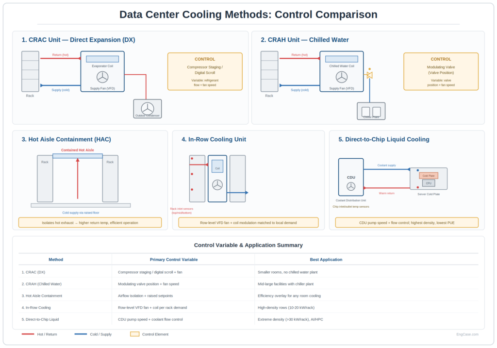
Five cooling topologies dominate contemporary data center design, each with a distinct control mechanism. The selection among them is driven primarily by rack power density and the availability of a chilled water plant.
2.1 CRAC vs. CRAH: The Foundation
While often discussed interchangeably, CRAC and CRAH units differ in their cooling mechanism, and this difference shapes the control strategy:
| Attribute | CRAC Unit | CRAH Unit |
|---|---|---|
| Cooling medium | Direct expansion (DX) refrigerant | Chilled water |
| Capacity control | Compressor staging / digital scroll | Modulating chilled water valve |
| Control variable | Refrigerant flow, fan speed | Valve position, fan speed |
| Typical response | Slower (compressor cycling) | Faster (valve modulation) |
| Energy efficiency | Lower at partial load | Higher with variable flow |
For chilled-water CRAH units, the control loop modulates a two-way or three-way valve and fan speed to track the supply air temperature setpoint. For DX CRAC units, capacity is managed through compressor staging or digital scroll technology, which introduces discrete control steps that demand careful tuning to avoid hunting.
2.2 Advanced Cooling Topologies for High-Density Loads
As rack densities exceed the practical limits of perimeter CRAC/CRAH cooling, three additional topologies have become standard in high-density and AI/HPC environments:
- Hot Aisle Containment (HAC): Rather than a cooling unit, HAC is an efficiency overlay that physically isolates hot exhaust air from the cold supply path. By preventing recirculation and bypass, containment enables higher return air temperatures and higher supply setpoints, which directly reduce chiller and compressor energy. HAC complements any of the air-based cooling methods.
- In-Row Cooling: Cooling units are positioned within the rack row, immediately adjacent to the heat source. VFD-driven fans and coil modulation respond to rack inlet temperature sensors at multiple heights, matching cooling delivery to localized demand. This topology is well suited to rows operating at 10–20 kW per rack.
- Direct-to-Chip Liquid Cooling: A Coolant Distribution Unit (CDU) circulates liquid coolant directly to cold plates mounted on the CPU or GPU package. Control is exercised through CDU pump speed and coolant flow regulation, governed by chip inlet and outlet temperature sensors. By transferring heat at the source and eliminating air resistance, this method achieves the highest heat density transfer and the lowest PUE, making it the preferred solution for racks exceeding 30 kW.
The following table summarizes the control variable and primary application for each method:
| Method | Primary Control Variable | Best Application |
|---|---|---|
| CRAC (DX) | Compressor staging / digital scroll + fan | Smaller rooms without a chilled water plant |
| CRAH (Chilled Water) | Modulating valve position + fan speed | Mid-to-large facilities with a chiller plant |
| Hot Aisle Containment | Airflow isolation + raised setpoints | Efficiency overlay for any room-based cooling |
| In-Row Cooling | Row-level VFD fan + coil per rack demand | High-density rows (10–20 kW/rack) |
| Direct-to-Chip Liquid | CDU pump speed + coolant flow control | Extreme density (>30 kW/rack), AI/HPC |
3. Core Control Principles for Data Center Cooling
3.1 Supply Air vs. Return Air Control
The single most consequential decision in air-based cooling control architecture is the selection of the control reference point:
- Return air control (legacy): The unit modulates capacity to maintain a fixed return air temperature. This method is simple but allows server inlet temperatures to drift as load distribution changes, and it conceals hot spots.
- Supply air control (modern best practice): The unit modulates capacity to maintain a fixed supply (discharge) air temperature. This approach directly governs the air delivered to the cold aisle, providing tighter inlet temperature control and enabling higher, more efficient setpoints.
Supply air control, combined with cold-aisle/hot-aisle containment, is the foundation of contemporary high-density cooling design.
3.2 Variable Frequency Drive (VFD) Fan Control
Fan energy scales with the cube of fan speed, making VFD-driven fan control the highest-leverage efficiency measure in air-based cooling systems. Key design considerations include:
- Differential pressure control: In raised-floor environments, VFD fans modulate to maintain a target under-floor static pressure, ensuring adequate airflow to all perforated tiles.
- Inlet temperature reset: Fan speed responds to the highest measured server inlet temperature, scaling airflow to actual demand rather than a fixed maximum.
- Minimum speed limits: A floor speed prevents stratification and ensures baseline circulation even at low IT load.
3.3 Group Control and Demand Fighting
When multiple cooling units serve a shared space under independent control, a destructive failure mode emerges: one unit humidifies while an adjacent unit dehumidifies, or one cools while another reheats. This “demand fighting” wastes significant energy. Group control logic—implemented at the BMS or through networked unit controllers—coordinates units to share a common setpoint and stage capacity collectively, eliminating this conflict.
4. Sensor Placement and Instrumentation
Control quality is bounded by measurement quality. The placement and accuracy of temperature sensors determine whether the control system protects equipment or merely reacts to averaged, misleading values.
| Measurement | Sensor Type | Placement | Purpose |
|---|---|---|---|
| Server inlet temperature | RTD / thermistor | Cold aisle, rack face (top/middle/bottom) | Primary control reference |
| Supply air temperature | RTD (Pt100) | CRAC/CRAH discharge | Supply air control loop |
| Return air temperature | RTD (Pt100) | CRAC/CRAH return | Load monitoring |
| Under-floor pressure | Differential transducer | Raised floor plenum | Fan speed control |
| Chip inlet/outlet temperature | RTD / thermistor | Cold plate (liquid cooling) | Direct-to-chip flow control |
| Relative humidity | Capacitive polymer | Return air path | Humidity coordination |
ASHRAE recommends measuring inlet temperature at multiple rack heights because vertical stratification can produce a 5–10 °C difference between the bottom and top of a rack. Controlling to a single averaged point conceals the top-of-rack hot spots that cause equipment failures.
5. Governing Standards and Reference Framework
Data center cooling control intersects several authoritative standards and guidelines:
- ASHRAE TC 9.9 Thermal Guidelines for Data Processing Environments – Defines recommended (18–27 °C) and allowable thermal envelopes for IT equipment inlet air.
- ASHRAE 90.4 – Energy standard for data centers, establishing efficiency requirements for mechanical and electrical systems.
- Uptime Institute Tier Standard – Defines redundancy and concurrent maintainability requirements (Tier I–IV) that shape control redundancy design.
- NFPA 70 (NEC) – Article 645 (Information Technology Equipment) and Article 430 (Motors) for electrical installation.
- TIA-942 – Telecommunications infrastructure standard for data centers, including environmental specifications.
Designing the control system to satisfy the target Uptime Institute Tier directly affects the redundancy of controllers, sensors, and power feeds. A Tier III facility, for example, requires concurrently maintainable cooling, meaning control architecture must permit servicing any single component without interrupting cooling delivery.
6. Energy Efficiency and PUE Optimization
Power Usage Effectiveness (PUE)—the ratio of total facility energy to IT equipment energy—is the dominant efficiency metric in data center operations. Cooling typically represents the largest non-IT energy consumer, making cooling control strategy central to PUE reduction. Effective strategies include:
- Raising supply air setpoints: Operating at the upper end of the ASHRAE recommended envelope reduces chiller and compressor energy, provided inlet control is reliable.
- Airside and waterside economization: Sequencing economizer operation under favorable ambient conditions to reduce or eliminate mechanical cooling.
- Variable-flow chilled water: Coordinating CRAH valve modulation with variable-primary chilled water pumping to match flow to load.
- Containment with VFD fan reset: Combining aisle containment with airflow-matched fan control to eliminate bypass and recirculation losses.
- Liquid cooling adoption: For extreme densities, direct-to-chip cooling eliminates the air-handling energy penalty entirely, delivering the lowest achievable PUE.
Each measure must be validated against the facility’s redundancy requirements; efficiency gains cannot compromise the thermal ride-through capability required during a cooling failure event.
7. Troubleshooting Guide: Diagnosing Cooling Control Failures
The following table summarizes recurring failure modes in data center cooling control systems, with structured diagnostic procedures and corrective actions.
| Symptom | Probable Cause | Diagnostic Steps | Corrective Action |
|---|---|---|---|
| Server inlet hot spots despite adequate cooling capacity | Airflow bypass; missing blanking panels; tile misplacement | 1. Map inlet temperatures by rack height. 2. Inspect containment and blanking panels. 3. Verify perforated tile placement vs. load. | Install blanking panels; relocate tiles to high-load racks; close containment gaps. |
| CRAC units demand fighting (one cools, one reheats) | Independent control; no group coordination | 1. Compare setpoints across units. 2. Review humidity demand per unit. 3. Check BMS group control config. | Enable group control; unify setpoints; coordinate humidity control. |
| Supply temperature oscillation (hunting) | Aggressive PID tuning; valve hunting; compressor short cycling | 1. Trend supply air temp at 1-second resolution. 2. Inspect valve/compressor cycling. 3. Review PID gains. | Reduce proportional gain; lengthen integral time; add compressor cycle delay. |
| Under-floor pressure low at remote tiles | Excessive cable obstruction; fan speed too low; tile leakage | 1. Survey under-floor obstructions. 2. Verify VFD fan speed vs. pressure setpoint. 3. Check tile and cutout sealing. | Clear obstructions; raise pressure setpoint; seal unsealed cutouts. |
| Chilled water CRAH low capacity | Valve not fully opening; low delta-T; air-bound coil | 1. Verify valve command vs. position. 2. Measure chilled water supply/return delta-T. 3. Bleed air from coil. | Repair/replace actuator; investigate low delta-T syndrome; purge air. |
| Direct-to-chip coolant over-temperature | CDU pump underspeed; flow restriction; cold plate fouling | 1. Compare chip inlet/outlet delta-T. 2. Verify CDU pump speed command. 3. Inspect coolant flow rate. | Increase pump speed; clear flow restriction; service cold plate. |
A disciplined diagnostic sequence verifies airflow or coolant path integrity before adjusting control parameters. Many apparent control failures are, in fact, airflow management problems—bypass, recirculation, or obstruction—that no amount of controller retuning will resolve.
8. Redundancy and Failure Mode Control
Data center cooling must survive component failure without thermal excursion. Control architecture supporting redundancy includes:
- N+1 staging logic: Standby units automatically start when an active unit fails or when load exceeds the capacity of running units.
- Lead/lag rotation: Controllers rotate which units run lead versus standby to equalize runtime and verify standby readiness.
- Thermal ride-through coordination: During a chilled water interruption, control logic sequences thermal storage or transient operation to maintain inlet temperatures until cooling restores.
These behaviors must be tested during commissioning through controlled failure simulation, not assumed from design documentation.
9. Conclusion
The control system governing data center cooling—whether CRAC, CRAH, in-row, or direct-to-chip—is the determinant of thermal reliability, energy efficiency, and operational resilience. Supply air control combined with cold-aisle containment provides tighter inlet temperature regulation than legacy return air methods; VFD-driven fan control delivers cubic-law energy savings; group control eliminates the demand fighting that plagues independently controlled units; and rigorous sensor placement at multiple rack heights ensures the control system protects against the top-of-rack hot spots that conceal equipment risk. For the highest densities, direct-to-chip liquid cooling transfers heat at the source and achieves the lowest PUE.
For electrical design engineers, facility managers, and HVAC maintenance technicians, mastering data center cooling control yields measurable returns in three dimensions: reduced PUE, improved thermal stability, and verified redundancy. Adherence to ASHRAE TC 9.9 thermal guidelines, ASHRAE 90.4 efficiency requirements, and Uptime Institute Tier standards establishes the engineering foundation for a cooling system that sustains uptime under both normal and failure conditions.