Variable frequency drives are the dominant actuator in modern precision HVAC systems. They deliver the speed-modulated airflow that sustains differential pressure cascades in cleanrooms and the variable cooling capacity that tracks fluctuating server load in data centers. Yet the same six-pulse rectifier front end that makes a VFD energy-efficient is also a non-linear load that injects current harmonics back into the electrical distribution system. Left unmitigated, these harmonics distort the supply voltage, overheat transformers and neutral conductors, trip protective devices, and interfere with the sensitive instrumentation on which the facility depends.
This article provides a senior-engineering reference on VFD harmonic mitigation in mission-critical HVAC installations. It addresses the physical origin of drive-generated harmonics, the IEEE 519-2022 compliance framework, the comparative performance of the principal mitigation technologies, and a structured field methodology for diagnosing and resolving harmonic-related faults.
1. The Engineering Problem: Why VFDs Generate Harmonics
A standard VFD converts incoming AC to DC through a three-phase diode bridge, smooths it with a DC bus capacitor, and reconstructs variable-frequency AC through an IGBT inverter stage. The rectification process does not draw current as a smooth sinusoid. Instead, the diode bridge conducts only during the intervals when the line-to-line voltage exceeds the DC bus voltage, drawing current in sharp pulses twice per cycle per phase.
This pulsed current waveform, when decomposed by Fourier analysis, contains the fundamental 50/60 Hz component plus a series of harmonic components at integer multiples of the fundamental. For a six-pulse rectifier, the characteristic harmonics are the 5th, 7th, 11th, 13th, 17th, and 19th — the orders described by the relationship 6k ± 1, where k is a positive integer. The 5th and 7th harmonics dominate, and an uncorrected six-pulse drive typically produces current total harmonic distortion (THDi) between 35 % and 80 % depending on source impedance.
The consequences in a precision facility are direct and measurable:
- Voltage distortion at the point of common coupling (PCC) affects every other load sharing that bus, including particle counters, PLCs, and power supplies.
- Transformer overheating results from increased eddy current and hysteresis losses that scale with the square of harmonic frequency.
- Neutral conductor overload occurs because triplen harmonics (3rd, 9th) sum arithmetically in the neutral of a four-wire system, though balanced three-phase VFDs primarily produce non-triplen orders.
- Nuisance tripping of circuit breakers and premature capacitor bank failure follow from elevated RMS current and resonance amplification.
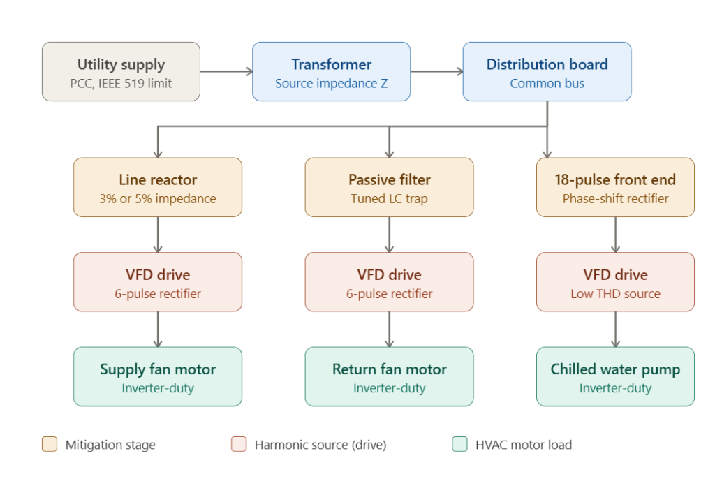
2. The Harmonic Mitigation Topology
The diagram above presents the single-line power path from the utility supply to the HVAC motor loads. The architecture illustrates the central engineering principle of harmonic management: mitigation is applied between the harmonic source (the VFD) and the shared distribution bus, so that distortion is suppressed before it propagates to other loads.
The power flows through five distinct stages:
- Utility supply at the PCC — the regulatory boundary at which IEEE 519 distortion limits are enforced.
- Transformer — whose source impedance directly influences the magnitude of voltage distortion produced by a given harmonic current.
- Distribution board — the common bus shared by all drives and by sensitive instrumentation.
- Mitigation stage — the line reactor, passive filter, or 18-pulse front end that suppresses harmonics at each branch.
- VFD and motor load — the harmonic source and the inverter-duty motor it drives.
The key insight is that the distribution board is the shared resource. Any harmonic current that reaches it distorts the voltage seen by every other connected device. Effective mitigation therefore happens upstream of this bus, at each individual drive branch.
3. IEEE 519-2022 Compliance Framework
IEEE 519-2022, “Recommended Practice and Requirements for Harmonic Control in Electric Power Systems,” is the governing standard for harmonic limits in North America and is widely referenced internationally alongside IEC 61000-3-12. The standard defines limits at the PCC, not at individual equipment terminals, which is a frequent source of design error.
3.1 Voltage Distortion Limits
For systems rated 1 kV and below, IEEE 519-2022 limits individual voltage harmonics to 5.0 % and total voltage harmonic distortion (THDv) to 8.0 %. These limits tighten as system voltage increases.
3.2 Current Distortion Limits
Current distortion limits are expressed as total demand distortion (TDD), referenced to the maximum demand load current rather than the instantaneous fundamental. The permissible TDD depends on the ratio of short-circuit current to load current (ISC/IL) at the PCC:
| ISC / IL | Max TDD (%) | Typical Facility Scenario |
|---|---|---|
| < 20 | 5.0 | Weak source, large drive load |
| 20 – 50 | 8.0 | Moderate source strength |
| 50 – 100 | 12.0 | Strong source |
| 100 – 1000 | 15.0 | Very strong source |
| > 1000 | 20.0 | Utility-class stiff bus |
A stiffer source (higher ISC/IL ratio) tolerates more harmonic current because the same current produces less voltage distortion. This is why two identical drive installations can have very different compliance outcomes depending solely on the strength of the upstream supply.
4. Comparative Analysis of Mitigation Technologies
No single mitigation technology is optimal for every application. The selection is driven by required THD performance, capital cost, footprint, and load profile. The following table summarizes the principal options.
| Technology | Typical THDi Result | Relative Cost | Footprint | Best Application |
|---|---|---|---|---|
| No mitigation (6-pulse) | 35 – 80 % | Baseline | Smallest | Non-critical, low-power, stiff source |
| AC line reactor (3 %) | 28 – 35 % | Low | Small | Basic protection, single small drive |
| AC line reactor (5 %) | 24 – 30 % | Low | Small | Improved baseline, multiple small drives |
| DC link choke | 28 – 40 % | Low (often integral) | None (internal) | Built into many modern drives |
| Passive harmonic filter | 5 – 12 % | Moderate | Moderate to large | Mid-power drives, fixed-speed operation |
| Active harmonic filter | < 5 % | High | Moderate | Variable loads, multiple drives on one bus |
| 18-pulse rectifier | 5 – 8 % | High | Large | High-power critical drives, aseptic suites |
| Active front end (AFE) | < 3 % | Highest | Moderate | Regenerative loads, strictest compliance |
4.1 Line Reactors and DC Chokes
Line reactors add series inductance ahead of the drive rectifier, slowing the rate of current rise and broadening the conduction interval. A 5 % reactor is a low-cost, robust first measure that also protects the drive from voltage transients. However, reactors alone cannot achieve IEEE 519 compliance on a weak source.
4.2 Passive Harmonic Filters
A passive filter is a tuned LC network shunted across the line, presenting a low impedance path to a targeted harmonic order (typically the 5th). Passive filters deliver strong THDi reduction at moderate cost but perform best at a fixed load point; their effectiveness diminishes as the drive operates away from its design load.
4.3 18-Pulse Rectifiers and Active Front Ends
An 18-pulse front end uses a phase-shifting transformer to feed three six-pulse bridges offset by 20 electrical degrees, cancelling the lower-order harmonics through phase superposition. Active front ends use a controlled IGBT rectifier to draw near-sinusoidal current and additionally permit regenerative braking. Both achieve the strictest compliance but at the highest capital cost and the largest footprint.
5. Troubleshooting Guide: Harmonic-Related Faults
The following table summarizes the most frequent harmonic-related failures in HVAC drive installations, structured from observed symptom to corrective action.
| # | Symptom | Probable Causes | Diagnostic Steps | Engineering Solution |
|---|---|---|---|---|
| 1 | Transformer running hot under normal load | High harmonic current loading; under-rated K-factor | Measure THDi with power analyzer; check transformer K-rating against harmonic spectrum | Install mitigation at drives; specify K-13 transformer |
| 2 | Nuisance breaker tripping with no overload | RMS current elevated by harmonics; resonance amplification | Capture current waveform; perform harmonic spectrum analysis | Add line reactors; verify no power-factor capacitor resonance |
| 3 | Particle counters or PLCs behaving erratically | Voltage notching and distortion at shared bus | Measure THDv at instrument supply; inspect grounding | Isolate sensitive loads; add mitigation; review SPG grounding |
| 4 | Power factor capacitor bank failing repeatedly | Harmonic resonance amplifying current into capacitors | Measure capacitor current; calculate resonant frequency vs harmonic orders | Detune capacitor bank with series reactor; relocate or remove |
| 5 | VFD tripping on DC bus overvoltage | Voltage distortion raising peak bus voltage; weak source resonance | Trend DC bus voltage; capture supply waveform during trip | Add line reactor; verify source impedance; check filter tuning |
5.1 Structured Diagnostic Methodology
A disciplined harmonic investigation follows a fixed sequence:
- Measure before modeling. Use a true-RMS power quality analyzer to capture the actual harmonic spectrum at the PCC and at the affected load, rather than assuming the spectrum from drive nameplate data.
- Identify the dominant orders. Confirm whether the 5th and 7th dominate (characteristic six-pulse signature) or whether unexpected orders point to resonance.
- Check for resonance. Calculate the parallel resonant frequency of any power-factor capacitors against the system inductance. Resonance near a characteristic harmonic order is the single most damaging condition and is frequently misdiagnosed as a drive fault.
- Verify the ISC/IL ratio. Determine the actual short-circuit capacity at the PCC before selecting a TDD target, because a weak source changes the entire compliance calculation.
- Select mitigation by load profile, not by THD alone. A variable-speed fan benefits from a different solution than a fixed-load pump.
The most common diagnostic error in the field is treating a resonance condition as a drive defect and replacing healthy drives, when the actual fault lies in an undetuned capacitor bank interacting with the system inductance.
6. Design Considerations for Inverter-Duty Motors
Harmonic mitigation addresses the supply side, but the inverter output also stresses the motor. The high-frequency PWM switching of the IGBT inverter produces voltage spikes that, on long cable runs, can reflect and reach twice the DC bus voltage at the motor terminals. Design countermeasures include:
- Inverter-duty motors meeting NEMA MG1 Part 31 or IEC 60034-25, with reinforced insulation systems rated for PWM voltage stress.
- Output dV/dt filters or sine-wave filters on cable runs exceeding the drive manufacturer’s threshold (commonly 30 to 50 meters).
- Shaft grounding rings to divert bearing currents induced by common-mode voltage, preventing electrical discharge machining (EDM) bearing damage.
- Shielded VFD cable with a symmetrical ground arrangement to contain common-mode emissions and protect adjacent signal cabling.
7. Conclusion
Variable frequency drives are indispensable to the energy efficiency of cleanroom and data center HVAC, but their non-linear rectifier front ends make harmonic management a mandatory engineering discipline rather than an optional refinement. The governing framework is IEEE 519-2022, which sets distortion limits at the point of common coupling and scales current limits to the strength of the source.
The mitigation hierarchy — from low-cost line reactors through passive filters to 18-pulse and active front ends — offers a continuum of performance and cost. The correct selection depends on the required THD target, the source strength, the load profile, and the sensitivity of co-located instrumentation. The financial case is unambiguous: the cost of mitigation hardware is modest relative to the cost of a transformer failure, an unplanned shutdown of a cleanroom or data hall, or the corruption of process instrumentation by voltage distortion.
Engineers who measure the actual harmonic spectrum, verify the source impedance, and check for capacitor resonance before selecting a solution consistently resolve harmonic problems at the first attempt. Those who treat symptoms in isolation — replacing tripping drives or overheating transformers without diagnosing the underlying distortion — repeat the failure at greater expense.
Related deep-dives on EngCase: Cleanroom HVAC Electrical Control in ISO Class 5 Environments; Data Center CRAC Control — Precision Cooling Strategy for High-Density Servers; Photolithography Cleanroom Cascade Control achieving ±0.1°C temperature precision.