Sensor placement pitfalls represent the single most common source of HVAC control system failure, yet they remain the least addressed during commissioning. The performance of any control system depends on the accuracy of its measurements. A perfectly tuned PID loop, a properly sized control valve, and a state-of-the-art building management system all become worthless if the sensor providing the input is reading the wrong value. Yet sensor placement is the single most overlooked aspect of control system commissioning, with errors that are introduced during installation persisting unnoticed for years and quietly degrading operational performance.
This article examines the recurring patterns of sensor placement failure in HVAC and process control. It addresses temperature sensor location, the dead zone problem in piping systems, insertion depth requirements for in-line sensors, and the diagnostic methodology for identifying measurement-driven control problems. The intent is to provide engineers, commissioning specialists, and facility managers with the practical knowledge required to verify that the measurement foundation of their control systems is sound before any tuning or troubleshooting effort begins.
1. The Hidden Foundation of Every Control Loop
Every control loop, regardless of its sophistication, operates on a simple principle: it compares a measurement to a setpoint and adjusts an output to minimize the difference. The measurement is therefore the foundation of the entire control function. If the measurement is wrong by 2 °C, the controller will drive the process to exactly that wrong value with mechanical precision.
This dependency creates a particular failure mode that is difficult to detect: the controller works perfectly, the actuator responds correctly, the operating logs look normal, and yet the actual process condition is not what the system thinks it is. Field investigators looking for control problems often spend hours analyzing PID parameters, communication networks, and actuator response curves before discovering that the sensor itself is the problem. The cost of this delay is paid every minute the system operates with a corrupted measurement.
1.1 Why Sensor Errors Are Hidden
Several characteristics of HVAC measurement systems make sensor placement errors particularly difficult to detect:
- The sensor reads a self-consistent value. Unlike a broken sensor that returns 0 °C or a maximum value, a mislocated sensor returns a plausible reading that simply does not represent the intended quantity.
- The control system responds correctly to its input. A controller faced with a 26 °C reading from a sensor in a 22 °C room will dutifully overcool the space to bring the reading down. The loop is functioning; the input is corrupted.
- The occupants compensate. Building users adjust their behavior — adding sweaters, opening windows, requesting setpoint changes — masking the underlying measurement error until someone investigates systematically.
- The records look acceptable. Trend data from a mislocated sensor often shows stable, well-controlled values. The error is in what the data represents, not in its statistical behavior.
For these reasons, sensor placement should be the first thing verified when troubleshooting any control problem, not the last. A 15-minute physical inspection of the sensor location often resolves what would otherwise become a multi-day tuning investigation.
2. Temperature Sensor Placement
Temperature is the most commonly measured quantity in HVAC systems, and temperature sensor placement is the most common source of measurement error. The same three principles apply to all temperature sensors: the sensor must be exposed to the fluid or air whose temperature is being controlled, it must not be influenced by heat sources unrelated to that fluid, and it must be representative of the bulk condition rather than a local anomaly.
2.1 Room Air Temperature Sensors
Room temperature sensors are arguably the most error-prone installation in any building. The first diagram contrasts a poorly chosen sensor location with a properly chosen one.
The incorrect placement positions the sensor on an exterior wall near a south-facing window, where solar radiation directly heats the sensor enclosure during daylight hours. The sensor reports a temperature several degrees higher than the actual room average, causing the variable air volume box to overcool the space.
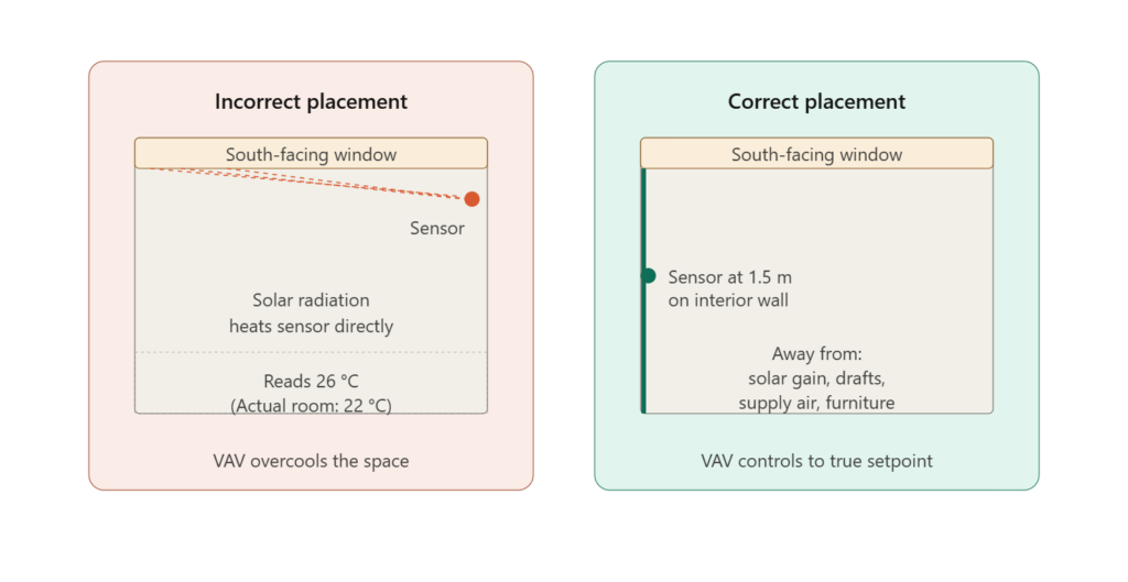
The correct placement positions the sensor on an interior wall, approximately 1.5 meters above the floor, away from solar gain, supply air diffusers, and heat-generating equipment. At this location, the sensor measures the average room air temperature that occupants actually experience.
Several specific factors must be considered when locating a room sensor:
- Solar radiation. Any sensor that can see the sun, or that is on a surface heated by the sun, will read high during daylight hours. South-facing exterior walls are particularly problematic in the Northern Hemisphere.
- Supply air streams. A sensor located in the direct path of the supply air diffuser reads the discharge air temperature, not the room temperature. The controller will then maintain the supply air at setpoint, not the space.
- Heat-generating equipment. Computers, copiers, lighting fixtures, and people all generate heat. A sensor adjacent to any of these reads a microenvironment, not the room.
- Furniture and partitions. Sensors placed behind or above furniture see still air at a different temperature than the occupied zone.
- Wall material and color. A sensor mounted on a wall that absorbs solar heat will read the wall temperature, not the air temperature.
Best practice locates each variable air volume box’s sensor in the space it serves, on an interior wall, at occupant breathing height, with adequate clearance from heat sources and air streams. When this is impossible due to architectural constraints, the deviation from ideal placement must be documented and the resulting bias accounted for in the control sequence.
2.2 Return Water Temperature Sensors
In hydronic heating and chilled water systems, the return temperature is often used as a control variable for circulating pump operation or for staging heating and cooling equipment. A common error places the return water sensor downstream of a makeup water connection, where ambient temperature water dilutes the actual return temperature. The sensor reads a value lower than the true return, and the pump or heating equipment cycles incorrectly.
The correct location for a return water sensor is upstream of any makeup water connection, in a section of pipe carrying the full return flow at full bulk temperature. The sensor must be downstream of any mixing valve outputs that should be reflected in the measurement, but upstream of any external influences that would bias it.
A related error involves return air or return water sensors installed in branches rather than headers. A sensor in a single branch reflects only the conditions of that branch, not the overall system. For overall system control, sensors must be located in the main header where all return flows have combined.
2.3 Process Fluid Sensors and Insertion Depth
Sensors installed in process piping, including cooling water, heating water, and steam lines, must penetrate the pipe wall to reach the bulk fluid. A common installation error uses a thermowell or sensor socket that is too short, leaving the sensor tip in the pipe’s boundary layer rather than the bulk flow.
The third diagram illustrates this problem. In a typical pipe, fluid near the wall moves slowly and exchanges heat with the wall material, while bulk fluid in the center moves at the design velocity at the true process temperature.
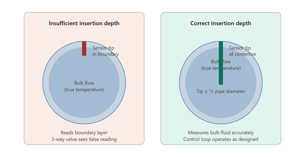
A sensor whose tip remains in the boundary layer reads a value influenced by the wall, not the bulk fluid. In a chilled water application, this typically produces a reading several degrees off from the true process temperature, leading the three-way mixing valve to position incorrectly and raising the supply water temperature above its setpoint.
Best practice requires that the sensor tip extend to at least the centerline of the pipe, ideally to a depth of one-half the pipe diameter or more. For pipes 100 mm in diameter and larger, a thermowell length of at least 50 mm beyond the pipe wall is typically required. The thermowell socket must also be insulated externally to the same standard as the rest of the pipe, to prevent heat loss to ambient air from biasing the reading downward.
3. The Dead Zone Problem
The second diagram illustrates one of the most insidious sensor placement failures: installation in a dead zone.
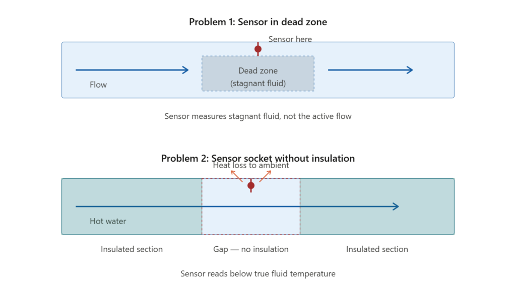
A dead zone is a region of piping or vessel where the fluid does not actively circulate. Common dead zones include the upstream side of closed valves, dead-end branches, bypass loops that are normally closed, and stagnant pockets in horizontal piping near elbows or tees.
A sensor placed in a dead zone reads the temperature of the stagnant fluid, which equilibrates with ambient conditions over time rather than reflecting the current process condition. The reading is stable, plausible, and completely wrong. Control loops fed by such a sensor exhibit slow response to changes, persistent offsets, and oscillation as the controller fights against an unresponsive measurement.
3.1 Insulation Around the Sensor Socket
A related failure mode affects sensors installed in actively flowing piping but without adequate insulation around the sensor mounting socket. The second diagram’s lower portion shows this configuration: the pipe is insulated on either side of the sensor location, but the sensor socket itself extends through a gap in the insulation. Heat loss from the exposed socket to ambient air conducts back through the sensor mounting, biasing the reading toward ambient temperature.
In a hot water system, this typically produces a reading several degrees below the true process temperature, leading the heating control loop to overheat the water in an attempt to reach setpoint. In a chilled water system, the bias produces the opposite effect, with the cooling loop undercooling. In both cases, the system operates at a steady-state offset that no amount of tuning will correct.
Best practice requires that sensor sockets be insulated to the same standard as the surrounding pipe. For high-temperature applications, the insulation may need to extend along the sensor body itself to minimize conduction losses. The transmitter or connection head should remain accessible for maintenance but should not provide a direct heat conduction path to ambient.
4. Pressure and Flow Sensors
Temperature sensors receive most of the attention in sensor placement discussions, but pressure and flow sensors suffer their own characteristic failure modes.
4.1 Static Pressure Sensors in Variable Air Volume Systems
Variable air volume systems use a static pressure sensor in the supply duct to modulate fan speed and maintain adequate pressure for downstream terminal boxes. The location of this sensor critically affects the system’s ability to deliver required airflow.
A common installation error places the static pressure sensor near the air handling unit’s discharge. At this location, the sensor reads the highest pressure in the system, which the fan can easily maintain. However, the sensor cannot detect when downstream branches starve, because by the time pressure drops at the remote terminal boxes, the sensor near the fan still reads acceptable values.
Best practice locates the static pressure sensor approximately two-thirds of the way down the main supply duct, at a location representative of the typical pressure condition needed to serve downstream terminals. The exact location is determined by the supply duct topology and the criticality of downstream branches, but the principle remains: the sensor must be where it can detect the pressure condition that limits system performance.
4.2 Flow Sensors and Straight Pipe Requirements
Inline flow sensors, including orifice plates, ultrasonic meters, and magnetic flow meters, require a minimum length of straight pipe upstream and downstream to operate accurately. The straight pipe length is necessary to allow turbulence from upstream fittings to dissipate and to ensure that the flow profile across the pipe cross-section is fully developed.
Installation in a location with insufficient straight pipe produces inaccurate readings whose direction and magnitude depend on the specific upstream disturbance. Errors of 5 to 10 percent are common, and in extreme cases the error can exceed 25 percent.
Typical requirements are 10 to 20 pipe diameters of straight pipe upstream and 3 to 5 diameters downstream, though specific requirements vary by sensor type. Manufacturer literature must be consulted for each installation, and if the available straight pipe is insufficient, flow conditioning hardware (vanes, perforated plates) must be installed to compensate.
5. Field Case Studies
The following cases illustrate recurring sensor placement failures encountered in industrial commissioning and operation. Identifying details have been generalized to focus on the engineering content.
Case 1: Cleanroom Temperature Control with Wandering Setpoint
A semiconductor cleanroom installation reported that one of three variable air volume boxes serving the same room consistently overcooled, while the other two operated correctly. Investigation traced the problem to the single room sensor installed for the entire space. The sensor was mounted on the exterior wall near a south-facing window. The other two VAV boxes, also taking their input from this sensor, were positioned such that their supply air reached the room average before reaching the mislocated sensor, while the third VAV’s supply air was deflected by furniture and never reached the sensor at all. The resolution was to install one sensor per VAV box at properly chosen interior locations.
Case 2: Chilled Water Plant Hunting
A commercial office building’s chilled water plant exhibited persistent oscillation in supply water temperature, with periods of 8 to 12 minutes. Multiple tuning attempts failed to resolve the hunting. Investigation found that the supply water sensor was located in a thermowell with a 15 mm insertion depth in a 200 mm pipe. The sensor tip was in the pipe’s boundary layer, reading a value influenced by the pipe wall temperature, which itself lagged the bulk fluid by several minutes. The resolution was to replace the thermowell with one extending to the pipe centerline, after which the loop tuned cleanly with standard parameters.
Case 3: Hot Water Distribution Offset
A district hot water system reported that the return temperature consistently read 3 to 4 °C below the value indicated by portable instruments at the same location. Investigation found that the sensor socket was exposed at a section where the surrounding insulation had been damaged during maintenance and not replaced. Heat loss through the socket biased the sensor reading downward. Restoring the insulation eliminated the offset.
6. Standards and References
Several engineering references address sensor placement requirements:
- ASHRAE Guideline 36 specifies recommended sensor placement practices for high-performance sequences of operation in HVAC systems.
- ASHRAE Handbook — HVAC Applications covers temperature and humidity sensor selection and placement in detail.
- ISO 16484 provides general principles for building automation and control systems including measurement requirements.
- ASTM E337 addresses humidity measurement methods including sensor placement.
- ISA-5.1 establishes instrumentation symbology and references measurement principles.
For specific applications, sensor manufacturers provide installation guidance covering straight pipe requirements, mounting orientation, and insulation practices. Vendor documentation must be consulted for each sensor type and verified against site conditions.
7. Troubleshooting Guide
The following table summarizes recurring sensor placement failures and their resolution.
| # | Symptom | Probable Cause | Diagnostic Step | Resolution |
|---|---|---|---|---|
| 1 | Room overcools during daylight hours | Sensor in solar gain path | Check sensor location at solar peak | Relocate to interior wall |
| 2 | Persistent offset from portable instrument | Sensor in boundary layer or dead zone | Inspect insertion depth, flow path | Replace thermowell, relocate sensor |
| 3 | Slow loop response despite normal tuning | Sensor in dead zone | Map sensor location vs flow path | Relocate to active flow region |
| 4 | Steady bias toward ambient temperature | Inadequate insulation around socket | Inspect insulation at sensor location | Restore insulation to socket |
| 5 | Flow reading fluctuates with no process change | Insufficient straight pipe | Measure upstream straight length | Install flow conditioner or relocate |
| 6 | VAV terminals starve at high load | Static pressure sensor too close to fan | Verify sensor location | Relocate to 2/3 duct length |
| 7 | One VAV in a space overcools, others normal | Single shared sensor in poor location | Inspect sensor location relative to each VAV | Install per-VAV sensors |
7.1 Structured Diagnostic Methodology
A disciplined sensor investigation follows this sequence:
- Verify the sensor against an independent reference. Use a calibrated portable instrument at the same location.
- Document the physical installation. Photograph the mounting, measure insertion depth, identify nearby heat sources.
- Examine the flow path. Trace fluid flow through the system to verify the sensor sees active flow.
- Inspect insulation continuity. A thermal imaging camera, where available, reveals heat loss paths through socket gaps.
- Compare to design intent. Verify that the sensor location matches what the control sequence assumes.
- Only then consider tuning or replacement. A correctly tuned loop with a corrupted measurement remains a corrupted loop.
8. Practical Field Checklist
For each temperature sensor installation:
- Sensor is on an interior surface or in a properly insulated socket
- No solar gain reaches the sensor at any time of day
- No supply air stream impinges directly on the sensor
- No heat-generating equipment is within 1 m
- Insertion depth reaches at least pipe centerline for in-line sensors
- Insulation is continuous around the sensor socket
- Sensor location is documented in commissioning records
- Reading agrees with a calibrated portable instrument within 0.5 °C
For each pressure sensor installation:
- Tap location reflects the pressure the control sequence intends to manage
- Tap is located in straight pipe with adequate upstream length
- Tap is oriented to avoid debris accumulation
- Pneumatic or hydraulic isolation valves are functional and open
- Tubing run is short and free of low points where condensate can collect
For each flow sensor installation:
- Manufacturer-specified straight pipe lengths are met upstream and downstream
- Flow conditioning hardware is installed where straight pipe is insufficient
- Sensor orientation matches manufacturer requirements (horizontal vs vertical)
- Calibration certificate is current and traceable
9. Conclusion
Sensor placement is the foundation on which every HVAC control function rests. A perfectly designed control sequence operating on a corrupted measurement produces wrong outputs with mechanical precision. The cost of poor sensor placement is paid continuously across the operating life of the installation, often hidden behind compensating behaviors that mask the underlying error.
The engineering principles required to place sensors correctly are well-established and not technically difficult. The challenge is the discipline of verifying placement against design intent during commissioning, documenting the result, and revisiting placement when control problems emerge. Many field problems attributed to tuning, network communication, or actuator failure are in fact sensor placement problems that were never identified.
For engineers commissioning new systems, the field checklist in Section 8 should be applied to every sensor before any control loop is tuned. For operators investigating control problems, sensor placement should be the first thing examined, not the last. The standards exist because the engineering principles do not change. The skill exists because installation conditions vary infinitely, and judgment is required to apply the principles to each specific situation.
Related deep-dives on EngCase: PID Tuning Methodology for HVAC and Process Control; Differential Pressure Cascade Control in Cleanrooms; Cleanroom HVAC Electrical Control in ISO Class 5 Environments; BMS Integration for Cleanroom and Data Center HVAC; Data Center CRAC Control for High-Density Servers; Photolithography Cleanroom Cascade Control; VFD Harmonic Mitigation in Cleanroom and Data Center HVAC.