The control valve is where the controller’s intent becomes physical action. A perfectly tuned loop driving a poorly selected or improperly sized valve produces unstable, inefficient, and damaging operation. Yet control valve selection is often delegated to vendor catalogs without the engineering analysis required to match valve characteristics to the process. The consequence is a class of recurring failures that no amount of tuning can resolve: oscillating loops, eroded valve trims, undelivered flow, and premature equipment failure.
This article provides a senior-engineering reference on control valve selection for HVAC and process control applications. It addresses the fundamental choice between two-way and three-way valves, the practical meaning of equal-percentage and linear characteristics, the calculation and selection of Cv, the consequences of cavitation, and the diagnostic methodology for identifying valve-driven control problems.
1. The Most Overlooked Decision in HVAC Design
Control valve selection involves multiple decisions that determine whether the valve will perform its function over the system’s operating life. These include valve body type (globe, ball, butterfly), characteristic (linear, equal-percentage, quick-opening), size (Cv), close-off rating, materials of construction, and actuator selection. Each decision interacts with the others, and the consequences of poor choices are paid continuously across operating life.
The most common selection error is sizing. Engineers often follow a rule of thumb based on pipe size, selecting a valve whose nominal diameter matches the pipe. This produces an oversized valve that operates near its closed position for most of its useful range, with poor controllability and accelerated wear on the seat. A correctly sized valve typically has a nominal diameter smaller than the pipe and operates with substantial pressure drop at design flow.
The second most common error is characteristic mismatch. A valve with a linear characteristic installed in a system that requires equal-percentage response produces an unstable loop that no PID tuning can resolve. The relationship between valve characteristic and process behavior is fundamental, and getting it wrong forces the controller to compensate for nonlinearity that should not exist in the first place.
1.1 The Cost of Bad Selection
The financial consequences of poor valve selection are direct and quantifiable. An oversized valve operating near its closed position experiences increased wear on the seat, leading to seat leakage and the need for premature replacement. A valve operating in cavitation erodes its trim within months. An undersized valve simply cannot deliver design flow, forcing the rest of the system to compensate through higher pump head and increased energy consumption.
For a typical commercial building, a single mis-selected chilled water valve can produce 5 to 15 percent additional pump energy consumption, valve replacement every 2 to 3 years instead of 10 to 15, and persistent control instability that requires regular re-tuning. Across a large building or industrial facility with dozens of control valves, the cumulative cost is substantial.
2. Two-Way vs Three-Way Valves: The Foundational Choice
The first diagram contrasts the two principal valve configurations in HVAC applications. The choice between them is fundamental, affecting hydraulic design, pump sizing, energy consumption, and control behavior.
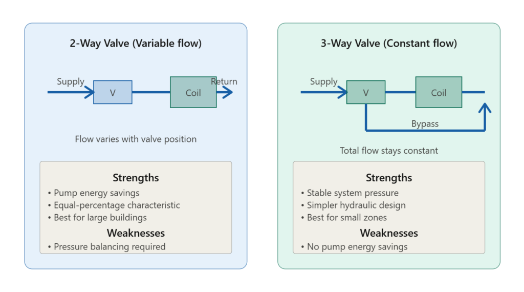
2.1 Two-Way Valves and Variable Flow
A two-way valve has a single flow path through the valve body. When the valve modulates, the flow through the connected coil or heat exchanger varies. As the valve closes, flow drops; as it opens, flow rises. This produces variable flow operation: the pump sees varying system resistance as the valve position changes, and pump energy consumption can be reduced when the valve is partially closed.
The characteristic naturally suited to a two-way valve installation is equal-percentage. As discussed in the next section, equal-percentage characteristic compensates for the nonlinear relationship between flow and heat transfer in water coils, producing approximately linear overall loop response.
Two-way valves are the standard choice in:
- Large hydronic systems where pump energy savings justify variable-flow operation
- Cooling tower water supply where flow control is desired
- Systems with multiple parallel coils where each can vary independently
- Modern variable-primary-flow chilled water plants
The principal challenge with two-way valves is pressure balancing. As one valve closes, the pressure differential available to other valves rises, potentially driving them open more than required and creating cascading instability. Properly designed two-way valve systems include pressure-independent control valves or pressure relief mechanisms to maintain stable pressure conditions.
2.2 Three-Way Valves and Constant Flow
A three-way valve has one inlet and two outlets (or two inlets and one outlet, depending on application). One outlet feeds the coil; the other bypasses the coil and rejoins downstream. As the valve modulates, the proportion of flow through the coil versus the bypass changes, but the total flow through the valve remains approximately constant.
The characteristic naturally suited to a three-way valve installation is linear. Because total flow is constant, the relationship between valve position and coil flow is essentially proportional, and linear characteristic produces direct controllability.
Three-way valves are the standard choice in:
- Small single-zone systems where pump energy savings are minor
- Steam-to-water heat exchangers where bypass control is required
- Systems requiring stable header pressure regardless of coil demand
- Legacy installations where retrofitting variable flow is impractical
The principal limitation of three-way valves is that they cannot provide pump energy savings. The pump continues to circulate full system flow regardless of demand, consuming the same energy whether the coil is fully active or completely bypassed.
2.3 Selection Criteria
The choice between two-way and three-way valves depends on system characteristics:
- Building size: Large buildings with significant pump energy benefit from two-way valves; small zones do not.
- Flow variation: Loads that vary significantly with time favor two-way valves; loads that are stable favor three-way.
- Pump availability: Variable-speed pumps require two-way valves to function effectively.
- Control complexity: Three-way valves are simpler to design and operate; two-way valves require more careful hydraulic engineering.
- Capital vs operating cost: Three-way valves have higher continuous operating cost; two-way systems have higher capital cost for pump variable-speed drives.
The general modern trend is toward two-way valves for buildings above approximately 1,000 m² of conditioned space, with three-way valves reserved for small zones, steam applications, and specific process requirements.
3. Valve Characteristics: Equal-Percentage vs Linear
The second diagram presents the two principal valve characteristics encountered in HVAC applications. The curves plot stem position against flow rate, showing how flow responds as the valve moves through its travel.
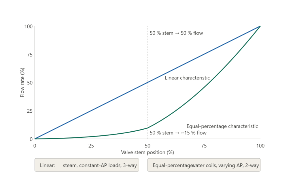
3.1 The Linear Characteristic
A linear valve produces flow proportional to stem position. At 25 percent stem position, the valve passes approximately 25 percent of its maximum flow; at 50 percent, approximately 50 percent; and so on.
Linear characteristic suits applications where:
- The process gain is constant across the operating range
- The pressure drop across the valve is a constant fraction of total system pressure drop
- Three-way mixing or diverting applications where total flow is approximately constant
- Steam control where flow is approximately proportional to pressure drop
Linear valves are simple to apply and intuitive to predict. The principal limitation is that they do not compensate for the nonlinear flow-vs-heat-transfer relationship in water coils, leading to control instability in systems where this nonlinearity is significant.
3.2 The Equal-Percentage Characteristic
An equal-percentage valve produces flow that increases more rapidly as the stem opens further. Equal increments of stem position produce equal percentage changes in flow rate. The curve is concave upward: at 25 percent stem, the valve might pass only 5 to 10 percent of maximum flow; at 75 percent stem, it might pass 60 to 70 percent.
This characteristic exists to compensate for two specific phenomena in real systems:
Heat exchanger nonlinearity. In a water coil, the relationship between water flow and heat transfer is nonlinear. Doubling the flow does not double the heat transfer; the marginal heat transfer per unit flow decreases as flow increases. An equal-percentage valve’s increasing-rate flow response approximately compensates for this decreasing-rate heat transfer response, producing an overall linear control characteristic.
Variable pressure drop. In a two-way valve system, as the valve closes and other valves remain open, the pressure differential available at the closing valve rises. A linear valve under these conditions would pass more flow than its position indicates. An equal-percentage valve’s response naturally compensates for this varying pressure drop.
Equal-percentage characteristic is the standard choice for two-way valves on hydronic water coils in HVAC applications. The combination produces stable, controllable operation across the load range.
3.3 The Consequence of Characteristic Mismatch
When a valve characteristic does not match the application, the controller is forced to compensate for nonlinearity that should not exist. The consequences include:
- Oscillation at certain operating points but stability at others
- Apparent need for different PID parameters at different loads
- Inability to control low loads (with linear valves on water coils)
- Sluggish response at low loads (with equal-percentage valves on constant-ΔP applications)
- Premature wear from constant hunting
A characteristic mismatch cannot be corrected by tuning. The valve must be replaced with the correct characteristic, or the controller must include compensation logic that approximates the missing characteristic.
4. Cv: The Single Number That Governs Everything
The Cv (flow coefficient) is the single most important parameter in valve sizing. Cv expresses the flow rate of water (in US gallons per minute) that passes through the fully open valve with a pressure drop of 1 psi. A larger Cv passes more flow at any given pressure drop; a smaller Cv passes less.
For water applications, the basic Cv calculation is:
Cv = Q × √(SG / ΔP)where Q is flow rate (gpm), SG is specific gravity (1.0 for water), and ΔP is pressure drop across the valve (psi).
In SI units, the equivalent Kv coefficient uses cubic meters per hour at 1 bar pressure drop:
Cv = 1.167 × Kv
Kv = 0.857 × Cv
4.1 Sizing for Authority
A correctly sized valve takes a substantial portion of the total system pressure drop at design flow. The valve authority β expresses this:
β = ΔP_valve / ΔP_total_circuitFor acceptable controllability, β should be at least 0.25, ideally 0.5 or higher. A valve with β below 0.25 operates with poor controllability across most of its travel; small stem movements produce large flow changes near the closed position, and the valve effectively operates as an on-off device rather than a modulating control element.
To achieve adequate authority, the valve must be sized smaller than the pipe in many applications. This is counterintuitive to engineers accustomed to matching valve diameter to pipe diameter, but it is necessary for proper controllability.
4.2 Practical Cv Calculation Examples
For an AHU chilled water valve passing 100 LPM at a design pressure drop of 0.3 bar:
Cv = 0.07 × LPM × √(SG / ΔP)
Cv = 0.07 × 100 × √(1.0 / 0.3)
Cv = 0.07 × 100 × 1.83
Cv ≈ 12.8
Select a valve with Cv just above this calculated value, typically the next standard size up. Avoid valves whose maximum Cv is significantly larger than required, because operation will then occur in the lower portion of the valve’s range where controllability is poorest.
For steam applications, the Cv calculation differs because steam is a compressible fluid:
Cv = W / (13.67 × √(ΔP × (P₁ + P₂)))where W is steam flow rate (kg/h), ΔP is pressure drop, P₁ is inlet absolute pressure, P₂ is outlet absolute pressure. The formula must respect the critical pressure drop limit, beyond which additional pressure drop produces no additional flow (choked flow).
5. Close-Off Rating, Rangeability, and Turn Down
Several additional parameters govern valve performance beyond Cv.
5.1 Close-Off Rating
The close-off rating is the maximum pressure differential across the closed valve that the actuator can maintain. If system pressure differential exceeds the close-off rating, the valve will not fully close and seat leakage will result.
In typical HVAC applications, close-off rating must equal or exceed the maximum pump shutoff head minus the minimum pressure on the downstream side. For systems with multiple pumps in parallel or with variable-speed drives operating at maximum speed, the maximum pressure differential can be substantially higher than design conditions. Underestimating this parameter leads to valves that leak when closed, producing unwanted flow that compromises system operation.
5.2 Rangeability
Rangeability is the ratio of maximum to minimum controllable flow:
R = Q_max / Q_minTypical industrial control valves have rangeability of 25:1 to 50:1. A valve with R = 30:1 and maximum flow of 100 LPM can control flow down to 3.3 LPM; below this, the valve cannot maintain stable control and operates in an unstable region.
For applications with significant load variation, rangeability must be evaluated against the minimum required controllable flow. Coils that must serve very low loads (such as winter cooling in temperate climates) require high-rangeability valves; loads that vary modestly may use lower-rangeability valves.
5.3 Turn Down
Turn down is similar to rangeability but expresses the practical controllable range of the specific installation, including effects of available pressure differential, actuator resolution, and process noise. Practical turn down is often less than the rated rangeability due to these real-world limitations.
6. Cavitation: The Silent Destroyer
The third diagram illustrates the cavitation mechanism that destroys valves operating with high pressure drops. Cavitation occurs when fluid pressure within the valve drops below the vapor pressure of the liquid at the operating temperature, causing vapor bubbles to form. Downstream, as the flow path widens and pressure recovers, the bubbles collapse violently against the valve internals or pipe walls.

6.1 The Mechanism
The pressure drop curve below the valve shows the phenomenon. Fluid enters at upstream pressure P₁. As it accelerates through the valve restriction, kinetic energy increases at the expense of pressure energy, and static pressure drops. At the point of minimum cross-section (the vena contracta), velocity is maximum and pressure is minimum. If this minimum pressure falls below the vapor pressure of the liquid, vaporization occurs and bubbles form.
Downstream of the vena contracta, the flow path widens, velocity decreases, and pressure recovers. The recovered pressure typically exceeds vapor pressure, and the bubbles condense violently back to liquid. Each bubble collapse produces a microscopic but high-pressure shock wave that impinges on whatever surface is nearby.
6.2 The Damage
Over time, the cumulative effect of millions of bubble collapses produces:
- Erosion of valve trim, plug, and seat surfaces
- Increased noise, often described as “gravel in pipes”
- Vibration that loosens fasteners and damages adjacent components
- Chemical attack from dissolved oxygen released by vaporization
- Eventual valve failure, sometimes within months of installation
The damage is cumulative and irreversible. A valve operating in cavitation cannot be saved by maintenance; the only remedies are replacement with a cavitation-resistant design (multi-stage valves, anti-cavitation trim) or reduction of the pressure differential through other means.
6.3 Preventing Cavitation
Cavitation prevention requires either avoiding the conditions that cause it or selecting hardware that tolerates them:
- Reduce maximum pressure differential across the valve through pressure-reducing stations upstream
- Select valves with low recovery coefficients (FL), meaning pressure recovery is gentle and minimum pressure stays above vapor pressure
- Use anti-cavitation trim that breaks pressure drop into multiple stages
- Operate the valve at lower percent open at design conditions to reduce velocity through the restriction
- For severe applications, use erosion-resistant materials (stellite, ceramic)
In HVAC applications, cavitation is most common in chilled water valves serving very low return temperatures (where vapor pressure is low) and in high-pressure industrial applications. Field investigation of any valve showing unusual noise, vibration, or premature wear should begin with cavitation as a leading suspect.
7. Interlock Failures in Heat Exchanger Control
A particular class of valve-related failure occurs at the boundaries between two control systems. Consider a heat exchanger where the primary side is heated by a central plant and the secondary side serves a building. When the building’s secondary pump stops (intentionally or through failure), the primary side must also be isolated, or hot water will continue to flow into the heat exchanger with no demand, raising secondary-side temperature and pressure beyond safe limits.
The mechanism that prevents this scenario is the interlock: a logical or electrical connection that forces the primary control valve closed whenever the secondary pump is not running. Without this interlock, the failure mode is severe — secondary water boils, pressure rises, relief valves open or piping ruptures, and water damage to occupied spaces below can be substantial.
The standard practice is:
- Specify normally closed (NC) control valves on the primary side, so loss of power produces a safe shutoff
- Interlock the primary valve open signal with the secondary pump running signal
- Verify the interlock during commissioning by stopping the secondary pump and observing the primary valve closing
- Inspect the interlock annually as part of preventive maintenance
A related interlock failure involves heating coils with electric pre-heat or re-heat elements. Without an interlock that disables the electric coil when the supply fan is off, the coil can overheat in stagnant air and cause fire. The interlock must include a time delay so that the electric coil de-energizes before the fan stops, preventing residual heat from finding stagnant air.
8. Field Case Studies
Case 1: Oscillating Cooling Coil Loop
A commercial building’s central cooling coil exhibited persistent oscillation that no PID tuning could resolve. Investigation revealed that the installed valve was a linear-characteristic three-way valve, while the application required equal-percentage characteristic for a two-way water coil. The original engineer had specified equal-percentage, but the contractor had substituted three-way during construction without notification. Replacing the valve with the correct two-way equal-percentage configuration eliminated the oscillation immediately.
Case 2: Premature Valve Failure on Chilled Water
A data center’s chilled water valves were failing within 18 months of installation, showing severe erosion of the plug and seat. Investigation showed that the valves operated at very low return temperatures (4 °C) with pressure differentials of approximately 4 bar across the partially closed valve. Calculations confirmed cavitation as the cause. Replacement with multi-stage anti-cavitation trim eliminated the failures.
Case 3: Boiler Room Steam Damage from Missing Interlock
A pharmaceutical facility experienced steam damage to a clean room when the primary steam-to-water heat exchanger continued to receive steam after the secondary pump tripped. Investigation showed that the primary steam valve had no interlock with the secondary pump and remained open. Steam pressure built up in the secondary side, ruptured a fitting, and water damaged equipment below. The resolution was to install a normally closed primary steam valve interlocked with secondary pump status.
9. Troubleshooting Guide
| # | Symptom | Probable Cause | Diagnostic Step | Resolution |
|---|---|---|---|---|
| 1 | Loop oscillates regardless of tuning | Characteristic mismatch | Verify valve characteristic vs application | Replace with correct characteristic |
| 2 | Loop unstable at low load only | Oversized valve, low authority | Calculate authority β | Replace with smaller Cv |
| 3 | Valve cannot close fully | Insufficient close-off rating | Compare ΔP at shutoff to rating | Replace with higher close-off |
| 4 | Cannot deliver design flow | Undersized valve | Verify Cv at design conditions | Replace with larger Cv |
| 5 | Noise, vibration, eroded trim | Cavitation | Check ΔP and vapor pressure | Multi-stage trim or reduce ΔP |
| 6 | Process damage after pump trip | Missing interlock | Verify interlock during commissioning | Add interlock, specify NC valve |
| 7 | Stable at design, unstable at low load | Linear valve on water coil | Verify characteristic | Replace with equal-percentage |
10. Standards and References
- ISA-75.01 through ISA-75.08 — Control valve sizing equations and methodology
- ASHRAE Handbook — HVAC Systems and Equipment — Application guidance for HVAC control valves
- IEC 60534 — International standard for industrial-process control valves
- ANSI/FCI 70-2 — Valve seat leakage classifications (Class I through VI)
- API 553 — Refinery valve and accessories standards
Manufacturer-specific catalogs provide application-specific selection assistance, but the fundamental engineering principles must be understood independently of any vendor’s product line. A valve correctly selected from one manufacturer’s catalog is functionally equivalent to a valve correctly selected from another’s.
11. Conclusion
Control valve selection is the design decision that determines whether the control system can function as intended. A correctly selected valve operates stably across its load range, closes when commanded, opens to deliver design flow, and lasts the design service life. An incorrectly selected valve produces oscillation that cannot be tuned out, fails to control at low loads, leaks when closed, or destroys itself through cavitation within months of installation.
The engineering principles required to select control valves correctly are well-established and not technically complex. The challenge is the discipline of analysis: calculating Cv from design conditions, evaluating authority, matching characteristic to application, verifying close-off and cavitation conditions, and confirming that the selected valve will operate stably across the full load range. Engineers who treat valve selection as a catalog lookup miss most of the value; those who treat it as the structural decision it actually is produce systems that operate well year after year.
Related deep-dives on EngCase: Sensor Placement Pitfalls in HVAC Control Systems; PID Tuning Methodology for HVAC and Process Control; Differential Pressure Cascade Control in Cleanrooms; Cleanroom HVAC Electrical Control in ISO Class 5 Environments; Data Center CRAC Control for High-Density Servers; BMS Integration for Cleanroom and Data Center HVAC; VFD Harmonic Mitigation in Cleanroom and Data Center HVAC; Photolithography Cleanroom Cascade Control.