A building management system is the supervisory nervous system of a mission-critical facility. In cleanrooms and data centers, the BMS does not merely log temperatures — it coordinates differential pressure cascades, sequences chillers and air handlers, manages variable frequency drives, archives compliance data for regulatory audit, and raises the alarms that prevent contamination excursions or thermal shutdowns. The quality of the BMS integration determines whether these subsystems operate as a coherent whole or as a collection of isolated islands that fight one another.
This article provides a senior-engineering reference on BMS integration for precision HVAC environments. It addresses the layered control architecture, the communication protocols that bind the layers together, the network segmentation required for operational security, and a structured methodology for diagnosing integration failures.
1. The Engineering Problem: Why Integration Architecture Matters
In a poorly integrated facility, each HVAC subsystem operates with its own controller, its own setpoints, and no awareness of the others. The chiller plant does not know the air handlers have reduced load. The exhaust system does not coordinate with the supply system during a pressure transient. The result is energy waste, control instability, and a complete absence of the centralized visibility that regulatory inspection and incident response demand.
A well-architected BMS resolves this through a layered hierarchy in which each layer has a defined role, a defined response time, and a defined communication interface to the layers above and below it. The architecture must satisfy three simultaneous requirements:
- Deterministic control at the field level, where loops must close in milliseconds.
- Coordinated supervision at the system level, where subsystems are sequenced and optimized.
- Auditable visibility at the management level, where operators and inspectors require trend data and alarm history.
2. The Four-Layer BMS Architecture
The diagram above presents the four-layer hierarchy that structures a modern BMS. Data flows upward from the physical world to the operator, and commands flow downward from the operator to the physical world. Each layer is distinct in both function and timing.
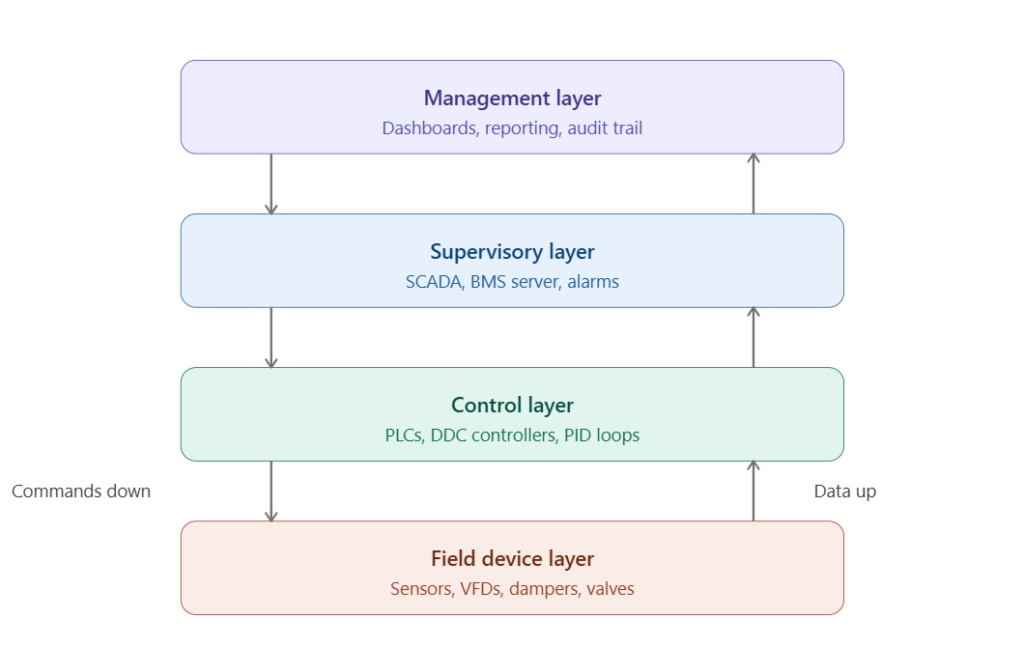
2.1 Field Device Layer
This is the boundary between the control system and the physical environment. It comprises the sensors that measure temperature, humidity, differential pressure, airflow, and particle count, alongside the actuators that execute control: VFDs, damper actuators, and modulating valves. These devices operate continuously and report to the control layer above.
2.2 Control Layer
The control layer hosts the PLCs and direct digital control (DDC) controllers that execute the closed-loop logic. PID loops for temperature, humidity, and pressure run here with deterministic scan cycles, typically between 10 and 50 milliseconds. This is the layer that actually maintains the process variables within their control bands; the layers above supervise but do not perform real-time control.
2.3 Supervisory Layer
The supervisory layer aggregates data from all controllers, executes alarm logic, sequences equipment across subsystems, and hosts the operator human-machine interface (HMI). SCADA software and the BMS server reside here. Cycle times at this layer are 1 to 5 seconds — far slower than the control loops, but sufficient for system-level coordination and human supervision.
2.4 Management Layer
The management layer provides dashboards, reporting, long-term trend archival, and the audit trail required by regulatory frameworks such as FDA 21 CFR Part 11 in pharmaceutical facilities. This layer is concerned with information, not control, and often interfaces with enterprise systems for maintenance scheduling and energy reporting.
3. Communication Protocols Across the Layers
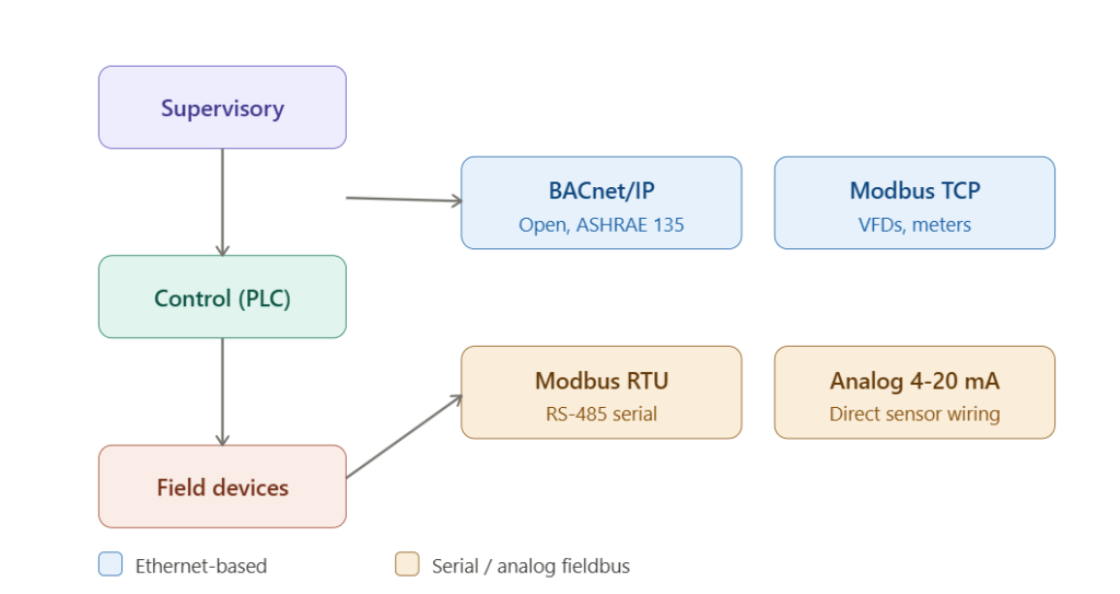
The second diagram maps the communication protocols to the layer boundaries they connect. Selecting the correct protocol at each interface is the central engineering decision in BMS integration, because it determines interoperability, scalability, and cybersecurity posture.
3.1 The Dominant Protocols
| Protocol | Type | Layer Boundary | Typical Use |
|---|---|---|---|
| BACnet/IP | Ethernet | Supervisory ↔ Control | Open BMS standard (ASHRAE 135) |
| Modbus TCP | Ethernet | Supervisory ↔ Control | VFDs, power meters, smart devices |
| OPC UA | Ethernet | Management ↔ Supervisory | Secure, platform-independent integration |
| PROFINET | Industrial Ethernet | Control ↔ Field | High-speed deterministic I/O |
| EtherNet/IP | Industrial Ethernet | Control ↔ Field | Allen-Bradley (CIP/ODVA) ecosystems |
| Modbus RTU | Serial (RS-485) | Control ↔ Field | Simple devices, multi-drop bus |
| BACnet MS/TP | Serial (RS-485) | Control ↔ Field | Field controllers, terminal units |
| Analog 4–20 mA | Direct wiring | Control ↔ Field | Single sensor or actuator signal |
3.2 Selection Principles
The choice is governed by a small set of principles:
- Open standards over proprietary protocols wherever feasible. BACnet (ASHRAE 135) avoids vendor lock-in and eases future expansion.
- Ethernet at the upper layers, fieldbus at the lower layers. The supervisory and management layers benefit from the bandwidth and routing of IP networks; the field layer often uses robust serial buses that tolerate electrical noise.
- OPC UA for cross-domain integration. When the BMS must exchange data with a manufacturing execution system (MES) or enterprise software, OPC UA provides a secure, structured, platform-independent bridge.
- Match protocol determinism to the control requirement. A safety-critical interlock requires a deterministic industrial Ethernet protocol; a temperature trend log does not.
A frequent integration error is mixing incompatible protocols at a single interface without a gateway, or relying on a proprietary protocol that cannot be extended when the facility grows.
4. Network Segmentation and Cybersecurity
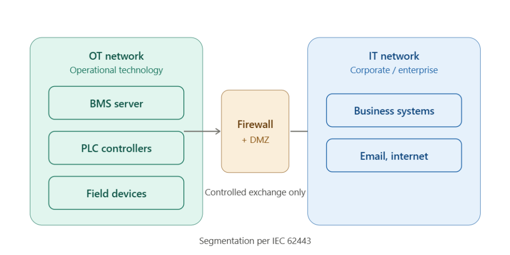
The third diagram illustrates the separation of the operational technology (OT) network from the information technology (IT) network. This separation is not optional in a mission-critical facility; it is a core requirement of the IEC 62443 cybersecurity framework for industrial automation and control systems.
4.1 Why OT and IT Must Be Separated
The OT network — the BMS server, PLCs, and field controllers — has fundamentally different priorities from the corporate IT network. OT prioritizes availability and determinism; a control packet delayed by a corporate email backup is unacceptable. OT devices also frequently run legacy firmware that cannot be patched as readily as corporate workstations, making them attractive targets if exposed to the internet.
4.2 The Segmentation Architecture
Effective segmentation follows these principles:
- Logical and, where feasible, physical separation of the OT network from the corporate IT network.
- A firewall with a demilitarized zone (DMZ) between the two networks, permitting only explicitly authorized data exchange.
- VLANs and managed industrial switches to isolate traffic within the OT network itself.
- No direct internet exposure of control devices; remote access, where required, passes through a hardened jump host or VPN.
- Unidirectional gateways for the highest-security applications, allowing data to flow out of the OT network for monitoring without permitting any inbound traffic.
4.3 The Compliance Basis
IEC 62443 defines security levels and zone/conduit models for industrial control systems. In regulated pharmaceutical environments, network security also intersects with data integrity requirements under 21 CFR Part 11, since the audit trail must be protected from unauthorized alteration.
5. Troubleshooting Guide: BMS Integration Failures
The following table summarizes recurring integration failures, structured from observed symptom to corrective action.
| # | Symptom | Probable Causes | Diagnostic Steps | Engineering Solution |
|---|---|---|---|---|
| 1 | Loss of BMS visibility for a controller | Network switch failure; IP conflict; protocol mismatch | Ping controller from supervisory workstation; inspect switch port; audit IP assignments | Replace failed hardware; assign static IP reservation; standardize protocol config |
| 2 | Intermittent data dropouts on a serial bus | RS-485 termination missing; cable length exceeded; address collision | Verify end-of-line termination; measure bus length; audit device addresses | Add termination resistor; shorten or repeat bus; resolve duplicate addresses |
| 3 | Alarms not reaching operators | Alarm priority misconfigured; notification routing broken; suppressed alarms | Review alarm configuration; test notification path; audit suppression logic | Correct alarm priorities; restore routing; remove erroneous suppression |
| 4 | Two subsystems fighting (e.g. simultaneous heat/cool) | Uncoordinated setpoints; missing sequencing logic; gateway data error | Trend both subsystems together; verify shared setpoint source; check gateway mapping | Implement sequencing logic; centralize setpoints; correct gateway register map |
| 5 | Gateway passing incorrect values | Register address offset; data type mismatch (16-bit vs 32-bit); byte order error | Compare raw register values to scaled output; verify data type and endianness | Correct register map; align data types; fix byte/word order |
5.1 Structured Diagnostic Methodology
A disciplined integration investigation follows a fixed order:
- Verify physical connectivity first. Confirm link lights, cable integrity, and termination before suspecting software.
- Confirm addressing. Duplicate IP or device addresses are among the most common and most overlooked faults.
- Inspect the gateway mapping. When two protocols meet at a gateway, register address offsets, data type mismatches, and byte-order errors silently corrupt data.
- Check protocol determinism against the requirement. A control function failing intermittently may be starved of bandwidth on a shared network.
- Audit the segmentation rules last. A newly blocked data path often traces to a firewall rule change rather than a device fault.
The most common integration error is misreading a gateway data corruption — a 32-bit value parsed as two 16-bit registers, or a byte-swapped float — as a sensor fault, leading to the replacement of healthy field devices.
6. Conclusion
BMS integration is the discipline that converts a collection of independent HVAC subsystems into a coordinated, auditable, and secure whole. The four-layer architecture defines where each function lives and how fast it must respond. The communication protocols bind the layers together, with open Ethernet standards favored at the upper layers and robust fieldbuses at the lower layers. Network segmentation, governed by IEC 62443, protects the operational technology that the facility depends upon.
The engineering value of a properly integrated BMS is realized in coordinated equipment sequencing, lower energy consumption, faster incident response, and a defensible audit trail. The cost of poor integration — subsystems fighting one another, blind spots in visibility, or an exposed control network — is paid in wasted energy, contamination excursions, and security risk. Engineers who treat integration as a system-level architecture, rather than as a series of point-to-point connections, build facilities that remain coherent and secure as they scale.
Related deep-dives on EngCase: Cleanroom HVAC Electrical Control in ISO Class 5 Environments; Data Center CRAC Control — Precision Cooling Strategy for High-Density Servers; VFD Harmonic Mitigation in Cleanroom and Data Center HVAC; Photolithography Cleanroom Cascade Control.