In a cleanroom, the most direct line of defense against contamination is not the HEPA filter or the air change rate — it is the differential pressure cascade. A correctly maintained pressure cascade ensures that air always flows from cleaner zones to less clean zones, regardless of door movement, occupancy, or transient events. When the cascade is lost, particles and microbial contamination migrate against the intended flow direction within seconds, and a single failure can compromise an entire batch in a pharmaceutical suite or a wafer lot in a semiconductor line.
This article provides a senior-engineering reference on differential pressure cascade control for precision cleanroom environments. It addresses the zone-level setpoint hierarchy, the closed-loop control architecture that maintains those setpoints, the dynamic response to door-opening disturbances, the energy implications of cascade design, real-world failure case studies, and a structured methodology for diagnosing cascade failures encountered in field operation.
1. The Engineering Problem: Why a Cascade, Not a Single Setpoint
A cleanroom is rarely a single isolated chamber. It is a sequence of progressively cleaner zones connected by airlocks, doors, and personnel transitions. If only the innermost zone were pressurized relative to the outside, the cleanroom would still draw air from every adjacent space whenever a door opened, and contamination would propagate inward through every personnel and material transfer.
A cascade design solves this by establishing a graduated pressure hierarchy:
- The highest grade zone holds the highest positive pressure.
- Each successively lower-grade zone holds a lower pressure.
- The outermost reference (corridor or unclassified space) sits at zero or near zero.
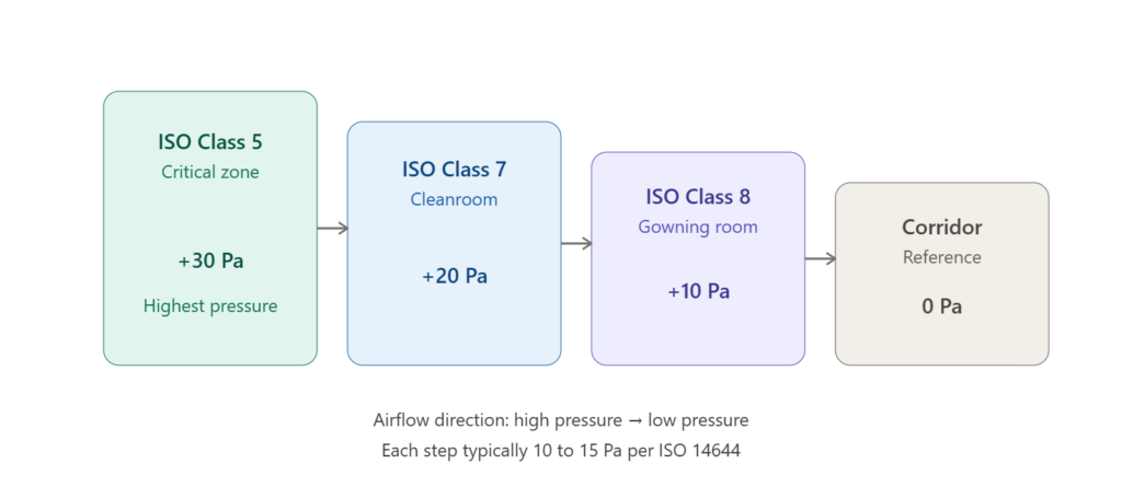
Air therefore flows continuously from clean to less clean, providing a contamination barrier that does not depend on door seals or operator behavior. ISO 14644-4 and EU GMP Annex 1 both codify this principle: typical step differentials of 10 to 15 Pa between adjacent grades, with absolute pressures often reaching +30 Pa or more at the critical zone. The cascade is the physical manifestation of the facility’s contamination control strategy, and it must be designed before any other HVAC sizing decision is finalized.
1.1 The Physical Basis
The mass flow of air through an opening of area A driven by a pressure differential ΔP follows approximately the orifice flow relation Q = Cd · A · √(2ΔP/ρ), where Cd is the discharge coefficient and ρ is air density. For a standard 2.1 × 0.9 m doorway, even a modest 10 Pa cascade drives several hundred cubic meters per hour through the opening — sufficient to overwhelm the diffusion of contaminants traveling in the reverse direction. Below approximately 8 Pa, this margin disappears and contamination ingress becomes possible during ordinary operation.
1.2 Regulatory Drivers
The legal and quality framework varies by industry but converges on the cascade principle:
- EU GMP Annex 1 (2022) mandates a minimum 10 Pa between adjacent classified grades in pharmaceutical sterile manufacturing.
- ISO 14644-4:2022 specifies cascade design principles for cleanroom installations of all classes.
- WHO TRS 961 Annex 5 sets equivalent expectations for global pharmaceutical operations.
- USP <797> for compounded sterile preparations specifies pressure differentials between buffer rooms and ante-rooms.
- SEMI E72 governs equivalent practices for semiconductor cleanroom design.
Each of these standards has been cited in regulatory observations and product recalls when the underlying cascade was found to be inadequate during inspection.
2. Zone Setpoint Hierarchy
The first diagram presents a four-zone cascade typical of a sterile pharmaceutical or semiconductor support area. The setpoints shown — +30, +20, +10, and 0 Pa — illustrate the principle, but actual values depend on the facility’s contamination control strategy, door areas, and supply airflow capacity.
2.1 Setpoint Selection Principles
The choice of step differential balances four competing engineering requirements:
- Robustness against door transients. Larger steps recover faster from disturbances because the cascade has more margin before it reverses.
- Operator comfort and door operability. Excessive pressure makes doors difficult to open (the force on a 2 m² door at 30 Pa is approximately 60 N) and creates acoustic whistling at gaps.
- Energy consumption. Maintaining higher pressures requires more supply airflow and conditioning energy, which scales with the cube of airflow under variable-speed fan operation.
- Equipment limits. HEPA filter housings, duct sealing tolerances, and damper authority bound the achievable cascade.
A 10 to 15 Pa step is the practical optimum for most installations. Steps below 8 Pa are vulnerable to door-opening reversal; steps above 20 Pa create operational and acoustic problems and consume disproportionate energy.
2.2 Negative Cascade for Containment
For zones handling hazardous materials — biosafety level 3 laboratories, cytotoxic compounding, certain semiconductor wet processes — the cascade is inverted. The hazardous zone sits at the lowest pressure, so air flows inward, containing the hazard within the room. The same engineering principles apply, only the direction is reversed.
Combined positive-and-negative cascades occur in mixed facilities: a sterile pharmaceutical fill zone (positive) adjacent to a hazardous active pharmaceutical ingredient handling zone (negative), separated by a sink airlock that is negative relative to both. These configurations require careful interlock logic to prevent reversal during simultaneous door operations.
2.3 Special Cases: Airlocks and Sinks
Airlocks between two graded zones can be configured in two ways:
- Cascade airlock — pressure between the two adjacent grades, used when the airlock is a transit space and air should flow continuously in one direction.
- Sink (bubble) airlock — pressure lower than both adjacent zones, used when neither zone should communicate with the other (e.g., separating two production batches with different products).
The control logic, setpoints, and door interlocks for these configurations differ fundamentally and must be defined during design rather than at commissioning. Retrofitting a sink airlock into a system designed for a cascade airlock requires significant rework of return air paths and damper authority.
2.4 Reference Selection
Every differential pressure transmitter measures against a reference. The choice of reference matters as much as the measurement itself:
- Direct corridor reference is simple but susceptible to corridor pressure variations.
- Stable plenum reference uses a common reference plenum across multiple zones, ensuring consistent cascade behavior.
- Atmospheric reference is used at the building perimeter but is sensitive to wind and stack effects.
A poorly selected reference produces a cascade that performs correctly in the BMS display but incorrectly in physical reality.
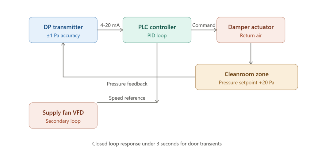
3. The Closed-Loop Control Architecture
The second diagram presents the closed-loop architecture that maintains a single zone’s pressure setpoint. The components are simple, but their tuning and interaction with adjacent zones determine the cascade’s stability.

3.1 The Primary Loop
The differential pressure transmitter measures room pressure against a stable reference (typically a corridor or pressure-stable plenum). It transmits a 4–20 mA signal — or increasingly a Modbus RTU or BACnet/IP digital value — to the PLC. The PLC compares the measured value to the setpoint and computes a PID output that drives a modulating return air damper actuator. By modulating the return airflow, the controller offsets the fixed supply airflow and establishes the desired pressure differential.
Sensor specification is critical at this layer. A typical ISO Class 7 cascade demands a transmitter with ±1 Pa accuracy, 1 second response time, and a calibrated range matched to the operating envelope (often 0–60 Pa or 0–100 Pa, never 0–500 Pa for cleanroom service). Over-ranged transmitters sacrifice resolution and produce noisy PID behavior.
3.2 The Secondary Loop
A secondary loop modulates the supply fan VFD to maintain duct static pressure. This loop responds more slowly than the damper loop and ensures that as multiple zones modulate their return dampers, the supply system delivers adequate airflow to all of them without starvation. The interaction between the room-level pressure loop and the duct-level static pressure loop is a frequent source of instability if both loops are tuned independently for fast response.
3.3 PID Tuning Considerations
Pressure control loops are fast-acting and prone to oscillation if mis-tuned. Practical tuning guidelines refined from cleanroom commissioning experience:
- Proportional band of 5 to 10 Pa for typical zones. A narrower band produces aggressive correction and hunting.
- Integral time of 30 to 60 seconds — too aggressive an integral term causes hunting; too slow leaves steady-state offset.
- Derivative term generally avoided in pressure loops because it amplifies sensor noise and creates spurious correction during sensor sampling jitter.
- Output rate limiting on the damper actuator to prevent overshoot during step changes — typically 1 to 2 % per second.
- Deadband of ±0.5 to 1 Pa around setpoint to prevent damper hunting during normal pressure fluctuations.
Ziegler-Nichols closed-loop tuning provides a starting point, but final values must be refined under live operating conditions with realistic disturbances including door events and adjacent zone interactions.
3.4 Damper Selection and Sizing
The damper is the final control element and frequently the limiting factor in cascade performance. Engineering considerations:
- Authority — the damper must produce meaningful flow change across its operating range, generally requiring a pressure drop across the damper of at least 25 % of total system loss.
- Characteristic — equal-percentage characteristic is preferred for pressure control because it provides finer modulation near closed position.
- Actuator speed — full-stroke under 30 seconds for routine zones, under 15 seconds for high-grade zones with frequent door operations.
- Position feedback — analog 4–20 mA feedback enables verification that commanded position matches actual position, exposing actuator failure early.
3.5 Multi-Zone Interaction
When multiple zones share a common supply or return system, their pressure loops interact. Closing one zone’s return damper reduces total return airflow and raises pressure in adjacent zones unless their dampers compensate. A well-designed cascade includes either:
- A common supply with adequate margin and individually decoupled return paths, or
- Coordinated supervisory logic in the BMS that anticipates inter-zone coupling.
Ignoring this coupling produces a cascade that is stable when only one zone changes but unstable when several zones modulate simultaneously, which is the typical condition during shift changes or batch transitions.
4. Door Transient Response
The third diagram illustrates the most important dynamic test for any cascade: the door-opening event. A door connecting two zones with a 20 Pa differential creates a sudden, large flow path between them. The pressure in the higher-grade zone collapses within milliseconds, and the controller must recover the setpoint quickly enough to prevent contamination ingress.
4.1 The Four Phases
The pressure trace exhibits four distinct phases:
- Steady state — pressure holds at setpoint with minimal variation, typically within ±1 to 2 Pa.
- Door open — pressure drops sharply as flow equalizes between zones. The drop depth depends on door area, cascade differential, and supply airflow margin. A drop to 30 to 50 % of setpoint is typical for a 2 m² door at 20 Pa cascade.
- Recovery — once the door closes, the controller drives the damper toward more restricted return airflow, raising the room pressure back toward setpoint. The recovery curve shape depends on PID tuning and supply margin.
- Steady state restored — pressure stabilizes at the original setpoint, often after a brief overshoot of 2 to 5 Pa.
4.2 Recovery Time Targets
ISO 14644-3 defines recovery as the time required to return within an acceptable band of the setpoint after a disturbance. For cleanroom pressure control, a recovery time under 5 seconds after door closure is the industry benchmark for grade B/ISO Class 7 and stricter zones. Longer recovery times indicate insufficient supply margin, inadequate PID tuning, or undersized damper actuators.
Recovery time is one of the few cascade performance metrics that can be measured non-destructively during operation, and it should be trended periodically to detect creeping degradation.
4.3 Design for Disturbance, Not Steady State
A common engineering error is tuning the cascade only for steady-state stability. A system that holds setpoint perfectly under quiet conditions may collapse for 15 to 30 seconds every time a door opens — long enough for substantial contamination migration. The cascade must be specified, tuned, and qualified against the worst-case door event, which in many facilities is the simultaneous opening of an entry airlock door during a material transfer.
4.4 Door Interlocks and Operator Discipline
No control system can fully compensate for both doors of an airlock opening simultaneously. Physical or electronic door interlocks are therefore part of the cascade design, not an optional accessory. Interlock logic typically permits one door to open only when the other is fully closed and the pressure has recovered to within a defined tolerance of setpoint. Operator override should be available only with audit trail logging.
5. Energy Implications of Cascade Design
A cascade is sustained energy infrastructure. Maintaining +30 Pa across a large cleanroom consumes meaningful HVAC energy continuously, and design decisions made at the planning stage determine the operating energy cost for the facility’s lifetime.
5.1 The Energy Equation
The fan power required to sustain a given pressure scales with airflow, and airflow scales with the square root of the pressure differential. However, the energy penalty extends beyond fan power: every cubic meter of supply air must be filtered, heated or cooled, humidified or dehumidified, and reheated for terminal trim. In a temperate climate the energy cost per supply air cubic meter is dominated not by fan power but by conditioning.
5.2 Optimization Strategies
Energy can be reduced without sacrificing cascade integrity through several engineering measures:
- Setpoint reset during unoccupied periods. Reducing the cascade from +15 Pa to +8 Pa during shift breaks saves substantial fan and conditioning energy. Particle counts must be verified to remain in classification during reset operation.
- Variable air volume terminals that modulate supply airflow with occupancy or process load while maintaining cascade.
- Energy recovery wheels and run-around coils on exhaust streams.
- Minimization of cascade steps consistent with risk. Removing an unnecessary intermediate grade simplifies the cascade and reduces conditioning load.
5.3 Commissioning for Energy
A cascade commissioned only for compliance frequently uses 20 to 40 % more energy than one commissioned for both compliance and efficiency. Energy optimization should be part of the commissioning protocol, not an afterthought addressed when utility bills become problematic.
6. Field Case Studies
The following cases illustrate failure modes and their resolutions in operational facilities.
6.1 The Reversed Reference
A sterile pharmaceutical filling room consistently failed annual qualification because the cascade direction reversed during personnel entry. Trend logs showed pressure dropping to zero or slightly negative within 2 seconds of door opening, never recovering until the door closed. Investigation revealed that during a recent transmitter replacement, the high and low pressure reference lines had been crossed at the connection block. The BMS displayed the setpoint correctly because the polarity was inverted in software to compensate for the previous installation error — when the new transmitter was installed, the compensation was now applied to a correct installation, producing inversion. Resolution required removing the software polarity inversion and physically verifying every reference line in the facility.
6.2 The Phantom Hunt
A semiconductor lithography support cleanroom exhibited 0.5 to 1 Hz pressure oscillation that resisted retuning. Multiple PID adjustments produced no improvement. Eventually a high-resolution data capture revealed that the oscillation matched the fundamental frequency of the supply fan VFD operating in sensorless vector control at a load point near a known resonance. The fan speed was shifted by 3 % through a minor setpoint adjustment, and the oscillation disappeared. The lesson: pressure loop hunting is not always a pressure loop problem.
6.3 The Recovery Time Drift
A pharmaceutical aseptic suite had been qualified for under 3-second door recovery at commissioning. Two years later, recovery had drifted to 12 seconds. The PID tuning was unchanged. Investigation traced the cause to gradual HEPA filter loading reducing supply airflow margin — the same controller that recovered quickly with a clean filter could no longer drive enough corrective airflow with a partially loaded filter. The resolution was both a filter replacement and a revised PID strategy that included supply pressure compensation.
7. Troubleshooting Guide: Cascade Failures
The following table summarizes recurring failures in differential pressure cascade systems, structured from observed symptom to corrective action.
| # | Symptom | Probable Causes | Diagnostic Steps | Engineering Solution |
|---|---|---|---|---|
| 1 | Pressure reversal during door opening | Insufficient cascade step; weak supply margin; slow controller | Trend pressure at 1 Hz during door test; measure damper response time | Increase cascade step; verify supply margin; retune PID |
| 2 | Sustained oscillation (±5 Pa hunting) | PID gain too aggressive; damper actuator hysteresis; sensor noise | Reduce proportional gain; capture actuator command vs position | Reduce gain by 50 %; extend integral time; replace actuator |
| 3 | Slow drift over hours | HEPA filter loading; supply duct leakage; sensor drift | Compare DP transmitter to portable reference; inspect duct seals | Replace loaded filter; seal duct; recalibrate or replace sensor |
| 4 | One zone permanently low | Return damper stuck; supply branch undersized; balancing error | Verify damper feedback vs command; perform supply airflow test | Service actuator; rebalance branch; adjust setpoint if necessary |
| 5 | Cascade reversed (lower grade higher than higher grade) | Transmitter reference lines swapped; setpoint entry error; BMS mapping error | Verify physical reference port routing; check BMS register values | Correct port assignment; verify all setpoints in BMS |
| 6 | Excessive recovery time after door event | Insufficient supply margin; loaded HEPA filter; conservative PID | Time recovery; trend supply duct pressure during event | Replace filter; add supply margin; retune for door event |
| 7 | Oscillation only during multi-zone events | Coupled multi-zone interaction; uncoordinated supervisory logic | Trend all coupled zones simultaneously; review BMS sequence | Implement coordinated supervisory logic; decouple return paths |
7.1 Structured Diagnostic Methodology
A disciplined cascade investigation follows a fixed sequence:
- Verify the sensor reference first. A reversed reference line produces the most confusing symptoms and is the single most common installation error in the field.
- Trend at high resolution. A 1-second trend log is essential to distinguish steady-state drift from transient response; many BMS default logging intervals of 1 minute are useless for cascade diagnostics.
- Test the door response deliberately. Open the door for a defined duration and time the recovery. Subjective observation is unreliable.
- Confirm damper position feedback. A commanded position that does not match actual position points to actuator failure, not control logic failure.
- Verify supply margin. A cascade that worked at commissioning may fail under loaded filter conditions even with identical tuning.
- Audit the BMS configuration last. Check that the setpoint displayed in the BMS matches the value actually used by the PLC; gateway mapping errors are insidious and produce confusing symptoms.
The most common diagnostic error is treating an oscillating loop as a sensor fault and replacing the transmitter, when the actual cause is PID gain that has never been retuned since commissioning, or supply margin that has degraded with filter loading.
8. Commissioning and Qualification
A pressure cascade must be formally qualified before the cleanroom is released for production. ISO 14644-3 defines the test methods:
- Pressure differential test — verify steady-state pressure between every pair of adjacent zones at multiple operating conditions.
- Recovery test — verify that the room returns to setpoint within a specified time after a defined disturbance.
- Visualization test — smoke or particle tracer demonstrates actual airflow direction at door openings, confirming that cascade direction is as intended.
- At-rest and operational classification — particle counts at multiple sample locations confirm the cascade actually achieves the contamination control objective.
These tests are repeated periodically throughout the cleanroom’s operational life, typically every 6 to 24 months depending on grade and regulatory requirement. The interval between qualifications is itself a regulated parameter in pharmaceutical operations.
8.1 Qualification Documentation
Each qualification test produces a signed and dated record retained for the operational life of the facility. In pharmaceutical applications, these records must satisfy 21 CFR Part 11 requirements for electronic signatures and audit trails. The records include:
- Equipment configuration at the time of test.
- Sensor calibration certificates traceable to a national metrology institute.
- Raw data captures, not only summary results.
- Deviations from protocol and their formal resolution.
A cleanroom whose qualification documentation is incomplete or inconsistent is treated by regulators as not qualified, regardless of how well the cascade actually performs.
9. Frequently Asked Engineering Questions
9.1 How frequently should cascade qualification be repeated?
ISO 14644-2 requires periodic monitoring; the specific interval depends on grade. ISO Class 5 and stricter typically require continuous monitoring with formal requalification every 6 months. ISO Class 7 and 8 typically require requalification every 12 months. Pharmaceutical EU GMP Annex 1 applies additional risk-based requirements that often shorten these intervals.
9.2 Can a cascade be retrofitted into an existing cleanroom?
Partial retrofits are common but engineering-intensive. The constraining factors are usually duct sizing, damper authority, and supply fan capacity rather than control logic. A retrofit study should include airflow modeling, not only equipment specification.
9.3 Why does the cascade drift over time?
The two dominant drift mechanisms are HEPA filter loading (reducing supply margin) and damper actuator wear (reducing positioning accuracy). Both are accelerated by high cycling rates and harsh operating conditions. Trending recovery time is the most sensitive early indicator.
9.4 What is the cost of cascade failure?
In sterile pharmaceutical manufacturing, a confirmed cascade reversal during a batch typically forces batch rejection and triggers a deviation investigation, with direct costs ranging from tens of thousands to several million dollars depending on batch value. In semiconductor manufacturing, cascade failure during lithography can damage entire wafer lots. The economic case for investing in robust cascade design is unambiguous at any reasonable cost of capital.
10. Conclusion
A differential pressure cascade is the contamination barrier that makes a cleanroom function as a system rather than a collection of filtered rooms. The zone setpoint hierarchy establishes the static defense; the closed-loop control architecture maintains it under steady conditions; the door transient response defines whether the cascade survives the realities of operational use; and the energy strategy determines what the cascade costs to sustain over its lifetime.
The engineering value of a robust cascade is realized at every door event throughout the cleanroom’s operational life. The cost of an inadequate cascade — pressure reversals, slow recovery, contamination excursions, batch failures — accumulates silently until a deviation or qualification failure forces investigation. Engineers who design, tune, and qualify the cascade against the worst-case disturbance, rather than the quiet steady state, build cleanrooms that remain in classification under real-world use, year after year.
The standards exist because the cost of ignoring them is recoverable only at much higher expense after the fact. Every engineering decision in cascade design is ultimately a choice about where in the lifecycle the cost will be paid.
Related deep-dives on EngCase: Cleanroom HVAC Electrical Control in ISO Class 5 Environments; BMS Integration for Cleanroom and Data Center HVAC; VFD Harmonic Mitigation in Cleanroom and Data Center HVAC; Photolithography Cleanroom Cascade Control; Data Center CRAC Control for High-Density Servers.